RELIABILITY CONSIDERATIONS FOR POWER SUPPLIES

Power supplies may not have the glamour, nor get the attention that processors and displays receive, but they are just as vital to system operation. A failed or marginal supply can bring a system to a halt or cause intermittent operation which compromises the end product and OEM’s reputation.
It’s not only outright supply failure that presents a cause for concern. A supply that is poorly designed or improperly built may degrade prematurely and cause inexplicable or misdiagnosed problems. In short, reliability is essential.
Here we look at reliability in power supplies, how it’s measured and how it can be improved.
RELIABILITY AND FAILURE RATE
Reliability, Failure Rate, and Mean Time Between Failures
The process of improving reliability begins by understanding the standard definitions and terms and it’s therefore important to note that reliability (R(t)) and failure rate (λ) are not the same thing.
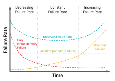
Reliability is the probability that the supply, operating under specified conditions, works properly for a given period of time. Failure rate is the percentage of units that fail in a given unit of time. It almost always follows a so-called “bathtub” curve, illustrated in Figure 1.
Two other useful measures are MTBF (mean time between failures, the inverse of failure rate) and MTTF (mean time to failure), defined as 1/λ. MTBF is useful for equipment that will be repaired and then returned to service, but despite the commonplace assumption, it does not guarantee a minimum time between failures, only a mean. MTTF is technically more correct mathematically, but the two terms are (except for a few situations) equivalent and MTBF is the more commonly used.
There is one more reliability-related term that needs clarification: service life. This is the amount of time that the supply needs to operate in its intended application. A long service life does not necessarily correlate to a long MTBF, and some applications require a large MTBF but only a short service life.
Failure Rate (λ)
As we can see in Figure 1, failure rate (λ) has three key phases: infant mortality, useful life and wear-out.
There’s a higher failure rate during the “infant mortality” phase, which usually lasts around low double-digit hours; these failures are generally due to poor workmanship and shoddy components, and can be found through pre-shipment burn-in.
The second, and longest, phase is “useful life,” during which the supply operates properly. During this phase the failure rate is low and constant.
The final phase is the “wear-out” phase, where the supply fails as its components reach the end of their operating life. Common mechanisms for wear-out include fan bearings going bad, electrolytic capacitors drying out, and stress cracks developing after thousands of thermal cycles.
Reliability
It’s not possible to predict with precision or certainty how long a specific power supply will operate or after how many hours it will fail. However, you can determine expected lifetime or likelihood of failure with high confidence using probability measures and techniques, a standard practice for electronic and mechanical components and systems.
A supply’s reliability is a function of multiple factors: a solid, conservative design with adequate margins, quality components with suitable ratings, thermal considerations with necessary derating, and a consistent manufacturing process.
To calculate reliability — the probability of a component not failing after a given time — the following formula is used:
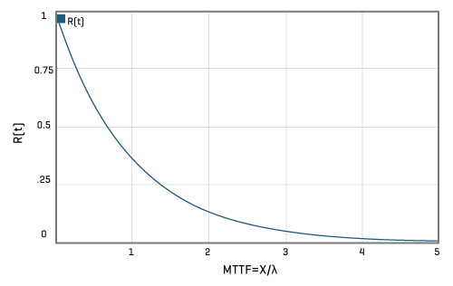
For example, the probability that a component with an intrinsic failure rate of 10-6 failures per hour wouldn’t fail after 100,000 hours is 90.5%, after 500,000 this decreases to 60.6% and after 1 million hours of use this decreases to 36.7%.
A similar formula can be used to calculate the reliability of a system:
Where λA is the sum total of all components failure rates:
Mean Time Between Failures – and 37%
Going through the mathematics can reveal interesting realities.
First, the failures for a constant failure rate are characterized by an exponential factor, so only 37% of the units in a large group will last as long as the MTBF number; second, for a single supply, the probability that it will last as long as its MTBF rating is only 37%; and third, there is a 37% confidence level likelihood that it will last as long as its MTBF rating.
Additionally, half the components in a group will have failed after just 0.69 of the MTTF.
DETERMINING THE FAILURE RATE
Failure Rate Calculation Methods
It is obviously not realistic to calculate failure rates by building many units and running them for many hours, under expected operating conditions. This is especially true for well-designed and properly built supplies, with extremely low failure rates, where the number of supplies and hours required to get valid results would be in the thousands.
Instead three methods can be used, prediction (during design), assessment (during manufacturing), and observation (during service life). No one method is inherently better than the others; each has strengths and weaknesses.
Prediction
Prediction uses one of several standard databases of component failure rate and expected life, among them are MIL-HDBK-217 (U.S. Navy), HRD5 (British Telecom), and Telcordia (previously Bellcore—the massive database from the experience of the former Bell Telephone System). The Telcordia process is detailed in Telcordia Technical Reference TR-332 “Reliability Prediction Procedure for Electronic Equipment.”
It is important to be consistent in the prediction methodology and database used for meaningful results. In general, MIL-HDBK-217 is focused on military and commercial applications, while the Telcordia document concentrates on telecommunications-oriented designs and applications. The MIL approach requires use of many parameters for the different components and includes voltage and power stresses, while Telcordia requires fewer component parameters and can also take into account lab-test results, burn-in data, and field-test data. Finally, the MIL approach yields MBTF data, while Telcordia produces FIT numbers, or failures in time, where FIT is a unit for expressing the expected failure rate; one FIT equals one failure per billion (109) device-hours (once in about 114,155 years) and is statistically projected from the results of accelerated test procedures.
However, use of these databases and techniques does not guarantee absolute accuracy, as it is based on assumptions which are somewhat incorrect, at best. It assumes that the design is perfect, the stresses are all known, everything is operated within its ratings, any single failure will cause complete failure, and the database is current and valid (in fact, databases are quite old and don’t have data on newer components).
Note that there are two ways to use prediction. It can be done by looking at the various stresses on each part, and how these stress affect the part’s expected performance and operating life. However, this approach is very time consuming and, instead, the simpler “parts count” method may be used. This approach groups similar components and then averages the factors for that group.
Supply designers must be careful when using these two approaches, as they generate different results. Again, it is very important to be consistent in approach and supporting database, even for parts count, as some parts may appear more favorable in one database compared to another. Some vendors will mix-and-match numbers to generate a better result they can cite, so users must ask the tough questions about any quoted numbers.
Then, why do it at all? By applying it consistently across different designs, it can indicate the relative reliability of their topologies and approaches, rather than their absolute reliability.
Assessment
Assessment is the most accurate way of predicting failure rate, but requires commitment and time. In assessment, a suitable number of final units are subject to accelerated life test at elevated temperature, with carefully controlled and increased stress factors. Of course, the risk is that some of these additional stress factors will cause premature failures and so this may not be a fair trial of the supply. The test must be done with calculated, proven impacts of the additional stresses.
In the Highly Accelerated Life Test (HALT) approach to assessment, a number of prototype units are tested under as many conditions as possible, with cycling of temperature, input voltage, output load, and other impacting factors. HALT testing is based on a simple basic principle: to fatigue a component, printed circuit board, subassembly, or finished product. You can either stress it at lower levels for many cycles, or use a higher level of stress for a fewer number of cycles.
Highly Accelerated Stress Screen (HASS) testing is an accelerated reliability screening technique which can reveal latent flaws not detected by environmental stress screening, burn-in, or other test methods. HASS testing uses stresses beyond initial specifications, but still within the capability of the design as determined by HALT.
The combination of variable thermal and simultaneous vibration stresses, in conjunction with product specific stresses, finds those defects and marginal products that traditionally were seen as “out of box” infant failures. The stresses in HASS are more rigorous than those delivered by traditional approaches, so HASS testing substantially accelerates early discovery of manufacturing-process issues. Reliability engineers can then correct the variations that would otherwise lead to field failures and greatly reduce shipment of marginal product.
It’s important to realize that full reliability assessment based on testing requires solid knowledge of statistics and associated analysis techniques, including issues such as levels of confidence assessment and Weibull multivariable analysis. For example, simply knowing that one supply failed after 50,000 hours in a group of 50 units under test is only the beginning step in analyzing the meaning of the data.
Observation
Observation in the field is also possible, but this is more difficult as it is impossible to control all the conditions a supply has been subjected to and therefore more difficult to undertake reliable causation analysis.
STRESSES THAT AFFECT POWER SUPPLY RELIABILITY
Power supply life is affected by three kinds of stress: thermal, mechanical, and electrical. A quality design anticipates each of these and takes necessary steps to minimize both their occurrence and their impact.
Thermal Stress
Thermal stress is the most challenging and insidious stress, because it manifests itself in so many ways. By their nature, supplies dissipate heat: a 1000 W supply operating at an admirable 90% efficiency is still producing 100 W of heat. But it is not just the supply’s own dissipation which causes the supply to operate at higher temperatures. Most of the power that the supply provides to the electronics eventually ends up as dissipated heat within the enclosure as well (some may be used outside the box to drive loads such as motors) therefore, adding to the overall thermal load and heat rise of the product.
Thermal stress takes two forms: static and dynamic. Static thermal stress means operation at elevated temperatures, which degrades components and their basic materials. Bulk capacitors may begin to dry out, or their seals may be stressed, and even resistor coatings may begin to deteriorate and break down. Interconnection and mating areas can expand and mismatch.
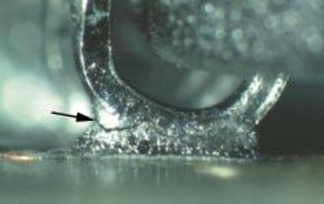
Dynamic stress is associated with the heating and cooling cycles which occur as the supply output goes from full load to low load, or is turned on and off. Each time this happens, the structures and connections expand and contract, and micro-cracks eventually develop due to differing coefficients of thermal expansion between materials, as seen in Figure 3. Such repeated cycling can cause outright breaks and failures. Note that the heating and cooling rate of these cycles will also affect their actual impact, so it is difficult to estimate the deterioration in product reliability they will actually cause.
Mechanical Stress
Mechanical stress severity depends on how and where the supply will be installed and used. This stress can cause both intermittent and hard failures, as cracks develop and circuit connections start to open and, in some cases, re-connect. Perhaps the supply is subject to vibration in normal use, or there is unexpected flexing of the circuit board, connections, or cabling. Mechanical stress can also result from an improper manufacturing process, such as a fastener which is over-torqued.
Electrical Stress
Electrical stress occurs when a component is operated beyond its rated value, either through poor selection or one-time events. For example, a capacitor may be rated to 100 Vdc, but sees a 150 Vdc spike in operation. Or a resistor is specified to handle up to 1 A current (corresponding to a specific maximum absolute peak-power level), but sees a higher-current pulse due to a circuit transient or external ESD event. The result is premature aging and early failure in many cases.
IMPROVING POWER SUPPLY RELIABILITY THROUGH DESIGN
Design Layout
Obviously, the paper design and topology should be robust and cautious. This should take into account the effects of load and line transients, as well as noise. The designer should also carefully determine the required minimum/maximum values of component parameters to ensure reliable operation (a “typical” value is nearly meaningless), as well as those for critical second- and third-tier parameters (including less-publicized factors in the magnetic components, such as temperature coefficient of some values).
SPICE (simulation program with integrated circuit emphasis) or similar modeling of the design is essential, using realistic, not simplified, models of the components and PC boards and tracks, to verify both static and dynamic performance.
Next, the choice of components must be done with conservative bias, with extra margin in both initial and long-term values for many of their specification values.
Finally, the layout must accommodate the fact that most supplies are dealing with significant current flows, on the order of 10, 20 or more amps. That means that PC tracks must be kept short to minimize voltage drop, extra-thick copper cladding may be needed, and bus bars may also be a good idea. Board lands need to be large enough for components and current, and through-holes need sufficient size and plating. None of these factors show up on the circuit schematic.
To minimize the effect of transients, self-inductance in layout pathways is also critical: a 2-inch straight run PC board track and a 2-inch winding track have the same dc resistance, but the latter will have much higher self inductance, which may affect closed-loop control stability, as well as transient performance, depending on supply operating frequency.

In summary, any time you have high currents, along with rapid changes in current, the design needs to be robust in layout and conductors, on current-carrying paths as well as ground paths.
Finally, thermal analysis of the design and its physical implementation is critical. This must validate the predictions on the anticipated overall temperature rise as well as localized hot spots which may occur due to “shadowing” of cooling air flow by large components located next to smaller, hotter ones, among other factors.
Circuit complexity is an indicator of potential unreliability. In general, every additional component in a circuit adds to component count and thus adds something that can fail. However, there is an argument to the rule that fewer components mean greater reliability: a missing component may be the one which helps ensure reliable long-term performance.
Component Selection
After design, the next critical step is selection of specific components and vendors. In addition to meeting the specifications called out by the designer, these components must be compatible with the manufacturing process. This may include need for mounting tabs, sufficiently large connection points and heavy wire leads, and screw terminals where appropriate.
Magnetic components (transformers and inductors), although conceptually simple, require extra attention as well. If they are not properly designed or assembled, or if their core halves are not glued properly, they can begin to vibrate at audio frequencies. Not only is this irritating to users, it also means that they can suffer fatigue-induced failures and fracture, sometimes even flying off the board.
Vendor credibility and conformance is key. The reason is that it’s difficult to distinguish, at first, a properly and consistently manufactured component such as a capacitor from a poorly made unit. Therefore, it is important to work with a competent vendor to ensure they have their materials sourcing and supply chain, manufacturing process, and qualification/verification properly documented and adhered to.
There are also generic component factors. By their nature some classes of components are more failure-prone than others. For example, fixed resistors are more reliable than variable ones (potentiometers), and film capacitors are more reliable than electrolytic ones.
Design for Manufacturability
Even if the design is solid and the BOM components are properly chosen from credible suppliers, the supply must be designed so that it can be assembled without compromising either the design or components. This means use of supports and brackets where needed, as many supply components are relatively large and heavy in contrast to more-common ICs, for example.
Even the basic soldering processes used in supply construction are an area for consideration. The common reflow-soldering temperature profiles are well established and understood for traditional lead-based solders. However, the regulatory mandate for lead-free (Pb-free) components and solder also means that a somewhat different reflow soldering profile is needed. The Pb-free process requires a higher peak temperature to ensure proper solder flow, wicking, and a reliable connection. Therefore, all components used must also be qualified to perform to specification after this higher reflow temperature and soak time.
IMPROVING POWER SUPPLY RELIABILITY THROUGH OVER SPECIFICATION
In addition to a cautious electrical design, the supply vendor can do many things to increase overall reliability.
Improved Components
Using components that are inherently more reliable — by their physics, their design, their materials, or their manufacturing and test process — can significantly reduce the overall risk but does add to the overall cost.
In power supplies the most common failure point is the capacitor and, therefore, using longer-life capacitors will have the greatest effect.
Redundancy
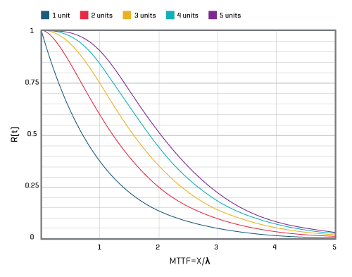
In basic redundancy, just N identical supplies are needed for the load, but N+1 are used in parallel, where N can be as low as one but is typically a number between two and six. If any one of the N units fails the remaining units can provide the required output current.
This approach works because the probabilities of more than one unit failing are quite low. For example, if the reliability of any single unit is 0.99, then the probability of both units failing is 0.9999 in an N=1 design, see Figure 5.
The N+1 method also brings higher up-front cost, of course, and often the need for hot-swap capability to replace the failed supply.
Derating
Using components at levels well below their rated specifications is a relatively simple method of enhancing efficiency.
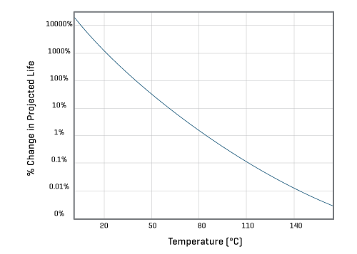
If we look at temperature, a component rated for reliable operation at 85°C will have a significantly improved efficiency if used at 55°C. Typically, a component’s life doubles for every 10°C decrease in temperature and this temperature-versus-life relationship is based on both the theoretical framework of the Arrhenius equation, which relates temperature and aging acceleration, plus a significant amount of industry test data.
Burn-In Testing
As per Figure 1, failure is more likely during the early stages of a components life than it is during its useful life. Burn-in testing weeds out units that would have failed early in the field and therefore would have brought down the overall reliability rating.
It’s worth noting that burn-in testing to weed out early failures is different to extended life testing. Burn-in identifies infant mortality-caused failures, which is especially helpful to avoid early field failures. Life testing via extended use of the supply will serve to validate reliability numbers, but it is not a substitute for thorough design analysis and production process.
Life testing is really part of the long-term product inspection process, and can provide useful feedback on the design and manufacturing process. For a well-designed and built supply, the number of long-term failures is relatively small and it is tricky to extrapolate from those small sets of numbers; small changes in underlying assumptions can lead to large differences in numerical analysis outcome.
Simplicity
Avoid fancy designs to minimize component count. Use established, proven approaches when possible, and minimize change in the next-generation or larger-capacity supplies; while relying as much as possible on what had been previously used, with a proven track record, and with manufacturing and test experience to support the design.
Thermal Management
As per the derating section and Figure 6, below, usage temperature has a significant effect on reliability, with the effect being based on chemistry’s Arrhenius equation, which is typically used to model the acceleration of the temperature dependent physical processes that lead to functional wear-out.
As can be seen from the Arrhenius Equation on the following page, minimizing temperature rise and temperature cycles is the most direct way to increase reliability, but this calls for carefully planned thermal management of cooling via one or more of the cooling modes: convection, conduction, and radiation.
Because it is dependent on how the customer mounts the supply, its enclosure, additional components in the enclosure, its ambient conditions, the use or non-use of active cooling such as fans, and other factors will often be beyond the OEM’s direct control.
The Arrhenius Equation:
In electronics, the Arrhenius equation is used to determine a component’s projected life operating at a given temperature. It is adapted from chemistry, where it measures reaction rate in relation to temperature.
- CR is the “Process Rate Coefficient”,
- M is an experimentally determined constant specific to the materials and methods used,
- e is the natural log (2.718281),
- Ea is the activation energy for the processes that lead to failure – typically 0.8eV to 1.0eV
- k is the Boltzman’s constant 8.617x10⁻⁵ ev k-1
- T is temperature (°K), typically at ambient room temperature (298.15°K, 25°C)
| Temp °C | Temp °K | Acceleration Factor | Projected Life |
|---|---|---|---|
| 25 | 298.15 | 0.001472615 | 67906.41% |
| 45 | 318.15 | 0.017011472 | 5878.39% |
| 65 | 338.15 | 0.147127089 | 679.68% |
| 85 | 358.15 | 1 | 100% |
| 105 | 378.15 | 5.549673616 | 18.02% |
| 125 | 398.15 | 25.92759997 | 3.86% |
The effect of a given temperature change on a components projected life can be measured using a small modification to calculate the acceleration factor:
- T1 is the reference temperature (e.g. 85°C / 358.15°K)
- T2 is the actual use temperature
- M is eliminated as it is constant for both experiments
If we use an assumed Ea of 1.0 for a component designed to run at 85°C, we can calculate the effect (1/AR) on the projected life of the component.
SUMMARY
At CUI we follow best practices to ensure our power supplies are among the industry’s most reliable. Reliable supply design is not a guessing game. A reliable supply requires suitable design and analysis, components, manufacture process, test, and installation. No single step will ensure a reliable supply, although there are many ways to decrease the supply’s reliability. When a vendor analyzes the supply’s expected reliability, it is important to be consistent in databases, models, environmental conditions, and manufacturing in order to yield meaningful results, which can be compared across different supplies and implementations.
