Criteria to Consider

There are a number of design criteria that an engineer must consider when selecting the appropriate low power dc-dc converter for their application. Aside from the general implementation of converting a dc input voltage to a dc output voltage, the engineer must understand the level of isolation required in the design, the tolerable voltage fluctuations that the architecture can withstand, and the types of protections that must be available. These variables, when combined with different packaging types, create a broad number of dc-dc converter options that an engineer must select from, including:
- Inputs / outputs
- Power conversion
- Isolation
- Regulation
- Protections
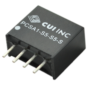
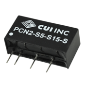
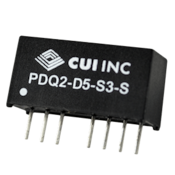
- Package
Input Voltage Requirements

The input of a dc-dc converter is tied to the output of an upstream supply in the power system. This will define the required input voltage necessary for the dc-dc converter. There are a number of different input options depending on the stability of the voltage. For example, a fixed input voltage can be used when the voltage rail connected to the input is very stable. If, on the other hand, the dc-dc converter is connected to a fluctuating supply, like a battery, then a much wider input range is required to account for the changing input voltage conditions. 2 to 1 and 4 to 1 type inputs are examples of wide input range devices used to address applications with a volatile input voltage. These numbers represent a comparison between the high and low input voltage limits. An example of a 2 to 1 input voltage device would be a dc-dc converter that has a nominal input of 12 volts but can operate anywhere between 9 volts and 18 volts while still maintaining a stable output voltage.
Available input ranges:
Fixed Output

The required output voltage is one of the easier decisions an engineer must make. The decision on the output voltage will be driven by the load requirements and whether the engineer wants to drive a single load or two loads.
Output voltage considerations:
- Single / Dual
- Positive / Negative
Isolation

Dc-dc converters can be implemented to provide isolation in a system. This electrical separation creates a barrier which can be used for safety protection or noise isolation. Two isolation factors are generally specified: isolation resistance and isolation voltage. The isolation resistance is a function of the material and spacing employed in the dc-dc converter. The isolation voltage is defined as the maximum voltage across the isolation barrier that a device can withstand for a fixed time period. The actual breakdown voltage is typically in excess of 1000 volts higher than the rated isolation voltage. The reason for rating a conservative isolation voltage is to ensure that the isolation testing of a supply does not degrade the isolation barrier in any way. The required isolation voltage will depend on the market the device is being used in. Industrial applications will typically accept 1 kilovolt of isolation where as medical applications may require up to 6 kilovolts of isolation. The higher isolation required in medical applications is implemented in order to comply with restrictive standards mandated by agencies like UL and TUV.


